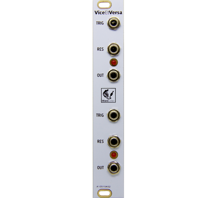
ViceEtVersa
How it works
ViceEtVersa was created for a friend, Gabriel Scotti, who wanted this feature to create rhythm patterns.
This module divides the clock frequency and works particularly well with rhythm generators. When a Clock (Gate, Trigger, LFO, …) signal arrives at the TRIG input, the output goes high (about 10v), so it will remain until the TRIG input returns to zero and a new signal arrives.
Each time a reset signal is detected at the RES input, the outputs will go to zero until the reset voltage disappears.
The two parts of the modules work in the same way. If no jack is plugged into input 2, output 1 is routed to the second unit.
ViceEtVersa can also be used as an octaver. If an oscillator enters the TRIG input, the output will be a square signal whose frequency is one octave lower than the incoming frequency. If no jack is plugged into input 2, output frequency 2 will be two octaves lower than the input signal. This function works particularly well with square signals.
Specifications
Width : 4hp (20mm)
Depth : 35mm
+12V : 7mA
-12V : 0mA
Input : Low : <0.5V / High: >0.5V
Output : Low : 0V / High: env. 10V
Depth : 35mm
+12V : 7mA
-12V : 0mA
Input : Low : <0.5V / High: >0.5V
Output : Low : 0V / High: env. 10V
Patch ideas
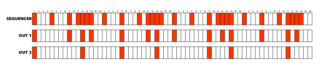
Basic: clock divider
– Connect the gate of a sequence on the input of ViceEtVersa. The output will output one step out of two (or one step on 4 if output 2 is used).
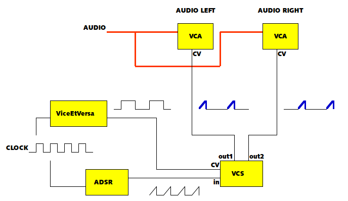
Ping-Pong effect: with a VCS (Voltage controlled switch), an envelope and two VCA
– Connect a ViceEtVersa.
– Connect the clock to the envelope.
– Connect the output of the envelope to a VCS (one input / two outputs) and the output of ViceEtVersa to the CV input of the VCS.
– Connect an audio source to the input of two VCAs. And the envelopes leaving the VCS on the CV input of the VCA.
– Connect the clock to the envelope.
– Connect the output of the envelope to a VCS (one input / two outputs) and the output of ViceEtVersa to the CV input of the VCS.
– Connect an audio source to the input of two VCAs. And the envelopes leaving the VCS on the CV input of the VCA.
Octaver (1 octave down and / or two)
– Connect the output of an oscillator to the input of ViceEtVersa. Output is a square wave an octave lower than the input. Output 2, two octaves.